

Views: 0 Author: Site Editor Publish Time: 2026-07-29 Origin: Site


An aluminum casting may look simple, but its mold is not. Every surface must survive pressure, heat, cooling, and repeated motion. Aluminum die casting molds begin as engineered digital systems, not blocks of steel. In this article, you will learn how designers turn part data into stable production tooling.
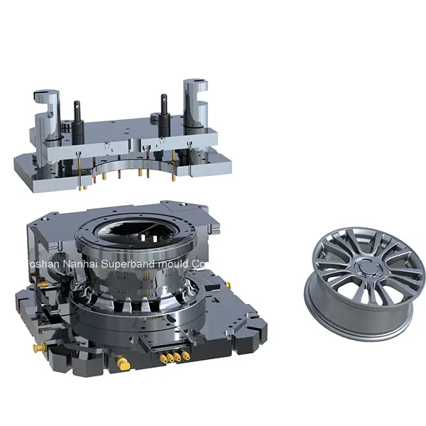
● Aluminum die casting molds are usually made from heat-resistant tool steel. The steel must handle pressure, wear, and rapid temperature changes.
● The process begins before any steel gets cut. Engineers review the part, alloy, volume, tolerances, and casting-machine requirements.
● Design for manufacturability helps prevent filling problems, distortion, difficult ejection, and unnecessary mold changes.
● Flow and thermal simulations guide the runner, gate, vent, overflow, and cooling designs. They also reveal likely defect areas.
● CNC machining, EDM, grinding, drilling, and polishing create the mold’s cavities and moving components.
● Trial casting is a key manufacturing stage. Engineers inspect samples, adjust the mold, and confirm stable process settings.
● Good aluminum die casting molds support repeatable quality, shorter cycles, easier maintenance, and lower lifetime production costs.
Manufacturing a die-casting mold follows a controlled engineering process. Each stage influences the next one. A poor early decision can cause expensive changes during testing.
Engineers begin with a three-dimensional part model and technical drawings. They review the alloy, tolerances, annual volume, surface needs, and machining areas.
They also study the available casting machine. Shot capacity, platen size, tie-bar spacing, and clamping force must suit the planned mold. Large structural parts need different tooling than compact housings.
Design for manufacturability, or DFM, checks whether the part can fill, cool, and eject correctly. Engineers examine wall thickness, ribs, bosses, fillets, draft angles, and undercuts.
Sharp thickness changes can create hot spots. Deep features may trap the casting during ejection. Early adjustments can prevent both problems.
Tip:Complete DFM before approving the mold design, since changes become costly after steel machining begins.
Designers divide the tool into fixed and moving halves. They then define cavities, inserts, cores, slides, ejector pins, and support plates.
The parting line receives special attention. It affects flash, visible surfaces, trimming, sealing, and machining allowances.
Engineers also choose the cavity count. More cavities may increase output, but they create greater balance and cooling challenges.
Casting simulation shows how molten aluminum moves through the mold. It can reveal trapped air, incomplete filling, cold joints, shrinkage areas, and uneven flow.
Thermal analysis shows where heat may collect. Engineers use the results to improve gates, overflows, vents, and cooling channels.
Stress analysis may also support large or highly loaded molds. It helps identify weak structures before manufacturing starts.
Most aluminum die casting molds use hot-work tool steel. It offers resistance to heat checking, erosion, mechanical stress, and repeated thermal cycling.
The best steel depends on production volume and part complexity. High-wear areas may use replaceable inserts. This approach can simplify repairs and reduce downtime.
Steel preparation may include rough cutting, stress relief, heat treatment, and hardness checks. Every step must follow a controlled process.
Machining often starts by removing large amounts of material. Rough CNC operations create the basic mold plates, pockets, and inserts.
Heat-treated components then receive precision finishing. High-speed CNC machines create curved surfaces and detailed cavity shapes.
EDM forms narrow slots, deep ribs, and internal details. Grinding controls flatness and fit. Drilling creates cooling lines and ejector holes.
Technicians install inserts, slides, cores, ejectors, guide parts, and hydraulic components. Each moving feature must travel smoothly.
They also inspect the parting surfaces. Poor contact can allow flash or metal leakage. Cooling and vacuum circuits receive pressure checks before testing.
The completed mold enters a suitable die-casting machine for its first trial. Engineers record injection speed, pressure, temperature, cooling time, and ejection performance.
They inspect the first samples for dimensions, porosity, flash, surface marks, incomplete filling, and distortion. Mold changes may follow these findings.
The team repeats this cycle until the mold produces acceptable parts consistently. Final approval should reflect both sample quality and process stability.
Manufacturing stage | Main purpose | Expected result |
Requirement review | Define technical and production needs | Clear mold specifications |
DFM analysis | Remove manufacturing risks | Castable part geometry |
Mold design | Build the complete tooling system | Approved digital mold |
Simulation | Predict flow, air, heat, and stress | Lower defect risk |
Machining | Produce accurate steel components | Finished cavities and mechanisms |
Assembly | Fit all mold systems | Functional production tool |
Trial and correction | Confirm quality and stability | Approved mold and process |
Several decisions must be complete before the mold enters production. They determine its size, complexity, cost, and expected service life.
The mold must match the behavior of the chosen aluminum alloy. Flow behavior, shrinkage, strength targets, and heat sensitivity can influence the tool design.
Geometry matters just as much. Thin walls require fast, balanced filling. Thick sections require stronger thermal control.
Machining allowances must also appear in the part design. They give later CNC operations enough material for final dimensions.
A single-cavity mold offers simpler control and maintenance. A multi-cavity mold may provide higher output per cycle.
However, every cavity must receive similar metal flow and cooling. Poor balance can create different quality levels within one shot.
The parting line should avoid critical surfaces where possible. It should also support reliable sealing and practical trimming.
Standard high-pressure casting suits many general components. Other parts may need vacuum-assisted, oxygen-filled, or ultra-low-speed processes.
Vacuum systems help remove cavity air. Ultra-low-speed filling may support smoother metal movement in selected structural applications.
The chosen process affects gate size, venting, thermal control, and equipment. It must be selected before the final mold release.
Precision machining transforms hardened steel into working mold components. The sequence must control both accuracy and material stress.
Rough machining creates plates, insert pockets, and basic cavity forms. It removes material efficiently while leaving a finishing allowance.
Stable fixtures protect reference points during each setup. These references help separate components align during assembly.
High-speed CNC machining produces complex three-dimensional surfaces. It works well for open cavities, smooth contours, and accurate profiles.
EDM removes metal through electrical discharge. It suits deep corners, fine ribs, narrow openings, and hardened components.
Grinding finishes shutoffs, guide surfaces, and flat contact areas. Polishing may improve release and visible casting surfaces.
Technicians inspect important dimensions after major machining stages. They compare finished features against the approved digital design.
Early inspection prevents small errors from spreading into assembly. It also protects the fit between plates, inserts, and moving cores.
A mold cavity alone cannot produce a stable casting. It needs systems that control metal entry, air removal, and heat transfer.
The runner delivers molten aluminum toward the cavity. The gate controls its final direction, speed, and distribution.
A gate must fill the part before early solidification begins. However, excessive speed may increase turbulence, trapped air, and erosion.
Engineers balance these risks through simulation and trial data. They also consider later trimming requirements.
Air inside the cavity must escape during filling. Vents provide controlled exit paths near the end of metal flow.
Overflows collect early metal, oxides, and trapped air. Their positions should reflect the expected filling pattern.
Vacuum equipment can remove more air before injection. It is often considered when internal quality requirements are demanding.
Cooling channels remove heat between casting cycles. They also guide how the aluminum solidifies inside the cavity.
Standard channels may be drilled through mold plates. More complex tools can use three-dimensional cooling structures near difficult hot areas.
Note:Uneven mold temperature can increase distortion, porosity, cycle time, and thermal fatigue.
Engineers review the complete gating, venting, and cooling layout together. These systems affect each other.
A cooling change may alter solidification. A gate change may move trapped air toward another location. Final simulation helps confirm the combined design.
Assembly turns separately machined components into one working tool. Skilled fitting remains important, even after accurate digital manufacturing.
Technicians mount the cavity inserts and core inserts into their plates. They install guide pillars and check mold alignment.
The two halves must close evenly. Shutoff surfaces need firm contact without unwanted interference.
Support blocks also require careful fitting. They help the mold resist clamping and injection forces.
Slides and core pulls form features that cannot release through normal opening. Hydraulic or mechanical systems control their movement.
Ejector pins push the solid casting from the moving half. Their positions must prevent bending, cracking, or deep surface marks.
Technicians test the complete movement sequence. A timing error can damage the mold during production.
Cavity surfaces receive the required finish. Some areas need polishing, while others need a controlled texture.
Cooling lines, vacuum circuits, and hydraulic connections undergo leak testing. Sensors, fasteners, and lubrication points also receive inspection.
The mold is then cleaned and prepared for machine installation.
A mold is not finished when machining ends. It is finished when it produces stable, approved castings.
Engineers confirm the machine can hold, fill, and operate the mold safely. They review clamping force, shot capacity, and platen dimensions.
The machine must also support slides, vacuum systems, and thermal controls. Poor machine matching can hide the mold’s true performance.
During the first trial, technicians record all major process settings. They then inspect the castings under controlled conditions.
Common checks include dimensions, flash, surface quality, filling, ejection marks, and internal defect risks. Machining tests may verify critical allowances.
An incomplete section may need a gate adjustment or different injection setting. Trapped air may require improved venting or vacuum control.
Persistent hot spots may need better cooling. Flash may indicate poor sealing, low support, or insufficient clamping.
The team should change one major factor at a time. This approach makes the results easier to understand.
Tip:Request trial reports and approved process settings before the mold leaves the supplier.
Final approval should cover the mold and its sample parts. It should also confirm a repeatable operating window.
Documentation may include inspection records, assembly drawings, maintenance guidance, and spare-part details. These records support installation and future servicing.
The basic manufacturing process remains consistent. However, each part creates different flow, cooling, and movement challenges.
Circular parts need balanced filling around their geometry. Uneven flow may create temperature differences or dimensional variation.
Engineers often focus on symmetrical runners, insert accuracy, and stable ejection. Cooling must also remain balanced around the cavity.
Motor and equipment housings may include ribs, bearing areas, mounting points, and internal passages. These features increase core and slide complexity.
Engineers must control air near deep pockets. They must also preserve enough material for precision machining after casting.
Cooling design becomes important around thick hubs and narrow walls. It helps control distortion and cycle time.
Long or wide structural parts create extended flow paths. They may also produce high projected areas during injection.
These molds need strong support, careful gate placement, and reliable thermal control. Multiple ejectors may distribute removal forces across the casting.
Large tools also require suitable handling and machine capacity. Early equipment planning prevents installation problems later.
Making aluminum die casting molds requires DFM, simulation, steel machining, assembly, trials, and controlled improvement. SUPERBAND supports product optimization, mold design, precision manufacturing, internal trials, and technical service. Its high-pressure molds support normal, vacuum, oxygen-filled, and ultra-low-speed processes. This integrated approach improves quality, startup speed, and long-term production value.
A: Aluminum die casting molds usually use heat-resistant tool steel for repeated thermal cycles.
A: Aluminum die casting molds undergo sample trials, inspection, and process adjustment before approval.
A: Aluminum die casting molds require precision machining, cooling systems, and extensive validation.
A: Poor cooling, weak venting, unsuitable steel, and unstable settings accelerate mold wear


