

Views: 0 Author: Site Editor Publish Time: 2026-08-14 Origin: Site


Transitioning chassis components to lightweight aluminum requires manufacturing methods ensuring structural integrity and crashworthiness. For hollow or complex geometries, Low-Pressure Die Casting (LPDC) stands as the undeniable industry standard. However, the true limiting factor always remains the tooling itself.
Modern subframes endure extreme dynamic loads every time a vehicle hits the road. Porosity or shrinkage defects caused by sub-optimal thermal dynamics within the tooling will render these critical structural parts entirely unusable. Precise thermal control dictates the ultimate success of the casting process.
Selecting the right mold architecture ultimately dictates cycle times, scrap rates, and overall project viability. This guide breaks down the essential engineering criteria you need for evaluating these complex designs. You will also discover key strategies for selecting a reliable manufacturing partner capable of delivering high-performance tooling on time.
Structural chassis parts demand high ductility and exceptional yield strength. Automotive engineers face a significant business problem when selecting a casting method. High-Pressure Die Casting (HPDC) often introduces trapped gas into the metal matrix. This turbulence severely limits subsequent heat treatment options. Blistering occurs if you subject gas-porous parts to high temperatures.
Here is where the LPDC advantage becomes clear. The process relies on controlled, low-turbulence filling from the bottom up. Slower injection speeds minimize oxide inclusions and virtually eliminate gas porosity. This clean microstructure allows manufacturers to apply full T6 heat treatments. You achieve the required mechanical properties through proper solutionizing and artificial aging.
These process dynamics create major implications for the tooling. LPDC uses much slower cooling rates and lower pressures than HPDC. Therefore, the mold itself must do the heavy lifting. It must control the exact temperature gradient across the part. The tooling must also feed liquid metal continuously to compensate for shrinkage during solidification.
| Process Feature | High-Pressure Die Casting (HPDC) | Low-Pressure Die Casting (LPDC) |
|---|---|---|
| Filling Speed | High (Turbulent) | Low (Laminar) |
| Gas Porosity Risk | High | Very Low |
| Heat Treatment | Often Restricted (T5 mainly) | Fully Capable (T6) |
| Tooling Thermal Role | Rapid Quenching | Controlled Directional Solidification |
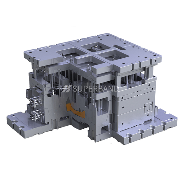
Engineering a robust tool requires strict adherence to baseline automotive subframe mold specifications. You cannot treat chassis tooling like standard commercial molds. Every physical parameter impacts the final microstructural integrity of the aluminum casting.
Subframe geometry dictates the gating strategy. Designers must choose between central or multi-point gating systems based on the flow length. Long, branching subframes often need multiple gates to ensure molten metal reaches all extremities before freezing. The design must also provide adequate feeding cross-sections. These risers compensate for the natural volumetric shrinkage of cooling aluminum.
Advanced thermal management determines ultimate part quality. Tool designers integrate highly localized air and water cooling channels throughout the steel blocks. The primary goal is directional solidification. The mold must force the liquid aluminum to cool from the extremities inward toward the gates. This precise cooling sequence pushes any potential shrinkage voids out of the structural component and into the runner system.
Extracting a massive aluminum subframe requires substantial force. Operators typically eject parts at temperatures exceeding 300°C. At this heat, aluminum remains soft and highly susceptible to warping. Tool designers must balance the ejector pin distribution perfectly. An even ejection force prevents part distortion and maintains critical mounting point locations.
Modern subframes feature complex webbing, deep ribs, and intricate mounting points. The tooling requires strict adherence to draft specifications to release these features smoothly. Insufficient draft angles cause galling, where aluminum adheres to the steel cavity. This defect damages the mold surface and ruins the casting finish.
Automakers continually push aggressive weight reduction targets. These goals often require hollow subframe sections instead of solid geometries. Creating these internal cavities necessitates placing inorganic sand cores within the mold before casting.
Integrating sand cores presents a unique engineering challenge. Liquid aluminum exerts massive buoyancy forces on submerged sand. Mold design must feature incredibly precise core prints to combat this. Core prints act as internal clamping fixtures. They hold the core securely in place to prevent any shifting during the metal injection phase.
Venting forms another critical challenge when utilizing sand cores. Inorganic binders release gases when exposed to molten aluminum. Advanced venting architectures must exist within the tooling to exhaust these core gases immediately. If gases remain trapped in the cavity, they form severe porosity defects inside the casting wall.
Tool designers also face the delicate balance of clearance and crushing. The core prints must offer dimensional tightness to hold the sand core securely. However, if the fit remains too tight, mold closure will crush the fragile sand. Crushed sand creates inclusion defects and dimensional failures. A high-quality lpdc production automotive subframe mold accounts for thermal expansion to ensure perfect core seating.
Unlike simpler brackets or generic housings, chassis subframes carry vehicle-specific requirements. Automakers engineer unique Noise, Vibration, and Harshness (NVH) characteristics into every chassis. They also calculate highly specific crash load paths. You cannot adapt a standardized tool for these applications.
Achieving these bespoke topological optimizations requires a custom automotive subframe mold. Every curve, rib, and thickness variation exists for a specific dynamic reason. The tooling must replicate this exact geometry while maintaining metallurgical soundness.
We achieve this precision through rigorous iterative design utilizing simulation software. Engineers never cut steel without comprehensive digital validation.
Prototyping phasing also plays a crucial role in custom tool development. Most automotive programs start with soft tooling or advanced sand casting methods. These initial phases provide physical parts for structural testing and NVH validation. Once physical testing confirms the CAD data, manufacturers confidently commit to high-cost production steel molds.
Procuring heavy-duty chassis tooling carries substantial risk. A generic toolmaker often lacks the metallurgical expertise required for low-pressure casting. You must evaluate potential partners based on strict automotive manufacturing criteria.
First, demand comprehensive engineering validation upfront. A qualified automotive subframe mold supplier will provide detailed flow and thermal simulation reports before project kickoff. If a vendor skips digital simulation to save time, they push the defect risk directly onto your production floor.
Second, verify their material competence. Tooling steel degrades under extreme thermal cycling. Ask for specific tooling steel grades. Industry best practice demands NADCA-compliant H13 steel or superior proprietary variants. Furthermore, the supplier must utilize advanced heat treatments to maximize the tool's resistance to thermal checking.
Third, assess their automation readiness. Modern foundries rely on high-efficiency robotic cells. The tooling must integrate seamlessly with automated core setting equipment. It must also feature robust gripping points for robotic extraction arms. Manual intervention during an LPDC cycle destroys consistency and harms safety.
Finally, scrutinize their compliance and quality assurance track record. The automotive industry operates on strict standards. Prioritize suppliers holding current TS/IATF 16949 certifications. They must demonstrate deep experience navigating the Production Part Approval Process (PPAP). Additionally, ensure they possess in-house dimensional metrology capabilities, such as advanced CMMs or 3D laser scanning equipment.
Deploying a massive automotive subframe mold onto the foundry floor introduces immediate production risks. Engineers must anticipate these variables to maintain steady output.
Thermal fatigue, often called heat checking, represents the primary failure mode. Molten aluminum repeatedly shocks the steel cavity. Micro-cracks eventually form on the tooling surface. These cracks transfer onto the finished casting as raised veins. You mitigate this risk through optimized cooling channel layouts and strict pre-heating routines. However, you must always factor periodic surface refurbishment into your maintenance schedules.
Cycle time creep poses another major implementation risk. Poor thermal management leads to longer solidification times. Even a thirty-second delay per shot drastically reduces your daily output. Foundries must monitor water cooling flow rates continuously to ensure the tool performs exactly as simulated.
High scrap rates can quickly turn a poorly designed tool into a production bottleneck. Misaligned core prints cause wall thickness variations. Inadequate venting leads to sudden spikes in porosity defects. When evaluating tooling options, use strict shortlisting logic. Prioritize vendors who guarantee specific cycle times and defect limits in the contract. Avoid selecting partners based solely on the lowest upfront machining cost, as technical failures quickly compound downstream.
The viability of an aluminum subframe program hinges entirely on the thermal and mechanical engineering of its LPDC tooling. If the tool fails to manage directional solidification, the resulting castings will lack the structural integrity required for automotive safety. Precision engineering remains the only path forward.
Engineers and procurement teams should take the following steps. First, finalize the structural CAD data and define annual volume requirements clearly. Second, demand comprehensive thermal simulation data as a strict prerequisite for any supplier shortlisting. Finally, prioritize tooling partners who demonstrate deep expertise in integrating complex sand cores and managing advanced automated extraction systems.
A: Depending on the steel grade, heat treatment, and maintenance schedule, a premium H13 steel mold typically yields 60,000 to 100,000 shots before requiring major refurbishment. Regular stress-relieving maintenance extends this operational window significantly.
A: Yes, but it requires highly sophisticated, localized cooling networks within the mold. Engineers must precisely control water and air flow to ensure thicker sections solidify properly without creating internal shrinkage cavities.
A: Standard lead times range from 10 to 16 weeks. This timeline strictly includes digital tool design, flow simulation, CNC machining, steel heat treatment, and initial T0 sampling on the foundry floor.
A: While HPDC is faster, LPDC allows for the use of sand cores to create hollow structures. Furthermore, the slow fill rate minimizes porosity, which is absolutely mandatory for parts requiring structural welding and T6 heat treatments.


