

Views: 0 Author: Site Editor Publish Time: 2026-09-14 Origin: Site


Accepting delivery of custom tooling represents a critical transfer of risk from the manufacturer to your facility. A defective mold does not just waste capital. It introduces dangerous structural vulnerabilities into the final product. It drives up cycle times and heavily inflates daily scrap rates. Before you sign off on a Factory Acceptance Test (FAT) and authorize the final payment to your tooling partner, you need a rigorous inspection protocol. You must rely on evidence-based data rather than visual assumptions.
This guide details the essential dimensional, material, and operational checks required to validate your tooling. A poorly vetted die will bottleneck your entire production line. It shifts the burden of correction directly onto your engineers. You will learn how to verify exact material hardness and audit precise dimensional accuracy. We also cover how to evaluate complex cooling systems. Finally, we explain how to assess T1 sample data properly before full-scale production begins.
Verify exact steel grades (e.g., H13) and heat-treatment hardness via independent metallurgical reports to ensure the die withstands high-tonnage impacts.
Audit the dimensional accuracy of the mold cavity against the approved 3D CAD models using Coordinate Measuring Machine (CMM) data.
Demand documented pressure testing of all cooling channels to prevent thermal fatigue and guarantee consistent cycle times.
Evaluate T1/T2 sample data strictly for flash, draft angle accuracy, and parting line mismatch before accepting the physical tooling.
Many manufacturers rush the mold acceptance process to hit aggressive product launch dates. This approach frequently backfires. Tooling defects discovered after installation lead to unplanned press downtime. They cause delayed time-to-market and trigger costly reverse logistics. You must catch these geometric and material errors at the supplier's facility.
Unlike a gravity aluminum auto wheel mold—which primarily manages gentle molten metal flow—a forging die absorbs immense mechanical shock. It faces extreme thermal stress during every single press cycle. Subpar steel will result in premature cracking. Inadequate hardening guarantees catastrophic die failure under high-tonnage impact loads.
A successful mold handover requires strict alignment between physical reality and engineering expectations. You must match the physical tooling conditions directly to the agreed-upon forged wheel mold specifications. Every contract tolerance must be verified through hard data. Relying on visual inspections alone exposes your production line to immense operational risk.
The core lifecycle of your die depends entirely on steel purity and heat treatment. You cannot evaluate these invisible factors visually. You must rely on scientific testing and documented certification to ensure durability.
Demand ultrasonic testing (UT) reports from your forged wheel mold supplier. This non-destructive test confirms the absence of internal voids. It reveals microscopic cracks hidden deep inside the raw steel block. A single internal void can split the die apart during its very first high-pressure strike. Always insist on Level 2 or Level 3 certified UT reports.
Check the Rockwell Hardness (HRC) across multiple zones. The cavity, core, and moving parts must match the engineering baseline. Most hot forging applications require 48-52 HRC. This specific hardness range resists wear while preventing plastic deformation. Test the surface hardness in at least five different locations to ensure uniform heat treatment.
Always cross-reference the steel mill certificates provided by the supplier. Match these documents to the actual block serial numbers engraved on the tool. This step prevents material substitution. It ensures you receive the exact premium H13 or equivalent tool steel you purchased.
Best Practice: Hire an independent third-party metallurgist to review the quenching and tempering heat-treatment logs.
Common Mistake: Accepting generic material certificates instead of demanding block-specific traceability documents.
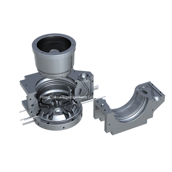
Precision remains non-negotiable in forging tooling. Minor deviations in the mold multiply into major balancing issues in the finished wheel. Structural problems often trace back to poorly machined die cavities.
Require a comprehensive Coordinate Measuring Machine (CMM) report. Inspect critical areas thoroughly. Focus specifically on the hub mounting pad, spoke draft angles, and the bead seat profile. The CMM data must overlay perfectly onto your approved 3D CAD model. Review the deviation maps carefully to spot machining trends.
Ensure machining tolerances align with established industry specifications. For high-performance alloy wheel mold tooling, tolerances must remain extremely tight. They often need to fall within ±0.02mm to guarantee uniform material distribution. Excessive dimensional drift causes uneven grain flow during the forging process.
Inspect the locking mechanisms and guide pins carefully. Any misalignment here causes a parting line mismatch. This defect generates excessive flash around the wheel perimeter. It forces you to perform heavy CNC post-machining on the forged blank, drastically slowing down your production speed.
Dimensional Inspection Checklist
Inspection Zone | Required Tolerance Range | Verification Method |
|---|---|---|
Hub Mounting Pad | ±0.02mm | CMM Probe |
Spoke Draft Angles | ±0.5 Degrees | Optical Laser Scan / CMM |
Bead Seat Profile | ±0.05mm | Contour Trace |
Guide Pin Clearance | ±0.01mm | Micrometer / Bore Gauge |
The surface finish dictates how easily the hot forged blank releases from the die. It heavily impacts the final cosmetic finishing required downstream. A poor surface finish creates friction, sticking, and premature tool wear.
Confirm all vertical surfaces have the correct draft angles applied. Inadequate draft will cause the hot aluminum to stick to the steel. This sticking leads to severe ejection damage. It drastically slows cycle times because operators must manually pry the blank free. You want a smooth, frictionless release every single time.
Inspect the cavity closely for machining marks or CNC chatter. Forged wheels always require secondary milling. However, deep tool marks in the mold transfer directly to the forging. These marks create dangerous stress risers in the forged aluminum structure. Smooth out any heavy milling steps before the tool undergoes final hardening.
If you specified a specialized surface treatment, verify it rigorously. Nitriding or PVD coatings require strict inspection. You must verify the coating thickness and uniformity using specialized magnetic or ultrasonic gauges. Proper coatings extend tool life by preventing aluminum galling on the die surface.
A mold must shed intense heat efficiently. If it cannot, it will bottleneck your entire forging press line. Thermal management directly determines your cycle time, part consistency, and overall tooling lifespan.
Every cooling line must undergo strict pressure testing. Water or oil channels should be tested at 1.5x operating pressure. Hold this pressure for a minimum of 30 minutes. This rigorous test guarantees there are no internal leaks or blockages inside the forged wheel mold. Internal leaks can cause catastrophic steam explosions during hot forging.
Check that the coolant flow rate matches the original design simulation. Measure the gallons per minute (GPM) exiting the tool. Uneven cooling creates severe temperature gradients across the die face. These gradients lead to residual stress, warping, and inconsistent grain flow in the wheel blank.
Manually and mechanically cycle the ejector plates multiple times. Movement must remain smooth without binding or halting. Pin clearances must stay tight enough to prevent aluminum extrusion during the heavy forging stroke. Loose pins allow metal flashing to shoot down the ejector holes, locking up the entire mechanism.
Best Practice: Use thermal imaging cameras during the FAT to map the heat dissipation across the die face.
Common Mistake: Ignoring minor pressure drops during cooling tests, assuming they are just faulty hose connections.
Never accept a mold based solely on the tooling's visual appearance. The first-shot (T1) sample tells the actual story. It proves whether the theoretical design works in physical reality under immense tonnage.
When analyzing T1 data, you must follow a strict, sequential evaluation process to uncover hidden flaws:
Measure the T1 forged blank for precise weight and overall concentricity.
Check strict dimensional adherence against the approved 3D CAD model.
Perform destructive sectioning to evaluate the internal grain structure flow.
Measure the thickness of the flash to gauge die closure accuracy.
Look closely for specific defect signatures. Signs of under-filling, cold shuts, or excessive flash serve as major red flags. They indicate poor material flow design. They often point to insufficient venting within the die cavity. Trapped air prevents the aluminum from filling the spoke cavities completely.
Use this comprehensive T1 data to issue a formal corrective action report. Only authorize the shipment of the mold after physical corrections are made. T2 or T3 samples must prove that all dimensional and material flow issues have been fully resolved. Never assume minor defects can be fixed on your own factory floor.
Accepting a forged wheel mold is a definitive commitment to your future production quality. By enforcing a rigorous inspection process, you transition from hoping for a good outcome to engineering a predictable one. Protect your capital investment by following these actionable next steps:
Enforce strict verification of material hardness and UT data before assembly begins.
Validate all dimensional CMM data against your original CAD files to ensure precision.
Demand physical proof of cooling channel integrity via sustained pressure tests.
Treat the T1 sample accuracy as the ultimate deciding factor for final tool approval.
Protect your operational budget by treating this inspection seriously. It is never a mere formality. It stands as your final, rigorous barrier against long-term manufacturing liability.
A: While it varies by design, high-quality forged tooling typically requires CNC machining tolerances of ±0.02mm to ±0.05mm. This strict range ensures structural uniformity. It severely minimizes balancing issues in the final forged wheel.
A: A gravity casting mold requires inspection focused on sprue design, gating, and porosity prevention. A forging die inspection heavily prioritizes impact resistance, HRC hardness, and draft angles for forced ejection. It requires extreme tolerance against severe mechanical fatigue.
A: A reputable supplier must provide native 3D CAD/CAM files and raw material steel certificates. They must supply heat-treatment logs, comprehensive CMM dimensional reports, and cooling channel pressure test results. They should also provide physical T1 sample inspection data.
A: Internal cooling regulates cycle times and prevents rapid thermal degradation of the mold steel. Discovering a blocked or leaking cooling channel after the mold is mounted in the press results in massive downtime. It drastically increases the risk of catastrophic tooling failure.


