

Views: 0 Author: Site Editor Publish Time: 2026-08-07 Origin: Site


Transitioning to large, integrated automotive pedal castings creates major manufacturing hurdles. Today, engineers face severe risks involving dimensional instability, localized porosity, and premature tooling fatigue during long production runs. Accurate sizing requires much more than simply measuring physical cavity dimensions on a blueprint. We must align machine clamping force, complex thermal dynamics, and strict material selection to guarantee high-yield production safely. Failing to address these interrelated factors leads to structural defects and costly scrap rates on the final assembly line. This article provides automotive engineers and procurement managers a definitive, step-by-step framework. You will discover exactly how to calculate foundational requirements and mitigate common design risks early in the process. We will also show you how to effectively vet certified partners for high-volume automotive pedal manufacturing successfully.
Modern automotive designs rapidly shift away from single pedal arms. We now see fully integrated mounting brackets and complex multi-pedal assemblies. Lightweighting initiatives for electric vehicles drive this structural evolution continually. This shift completely redefines what qualifies as a large pedal casting today. Standard sizing methods often fail when engineers apply them to these massive modules. Increased flow lengths cause molten aluminum to cool too rapidly inside the cavity. This premature metal solidification frequently leads to dangerous cold shuts.
Furthermore, higher volume-to-surface-area ratios severely exacerbate material shrinkage during cooling. They also increase the likelihood of extreme part warping upon ejection. Building a successful large castings automotive pedal die casting mold requires precise engineering foresight. The primary success criterion is achieving strict net-shape accuracy consistently. You must eliminate all critical-zone porosity to guarantee passenger structural safety. A brake pedal failure due to internal voids is catastrophic.
Concurrently, you need to maintain a cycle time well below standard OEM thresholds. These production thresholds typically hover between 45 and 60 seconds per shot. Engineers face immense pressure to balance this speed against perfect structural integrity. Common mistakes include ignoring localized hot spots until the first trial run. Best practices dictate resolving all thermal imbalances during the initial design phase.
Accurately calculating machine clamping force dictates your entire press selection strategy. You must first determine the exact total projected area of the casting. The standard formula framework remains very straightforward for mechanical engineers. Tonnage equals the projected area multiplied by cavity pressure, divided by 2000. However, complex geometries demand significant additional safety margins. Engineers should always add a 15% to 20% safety factor for these integrated assemblies. This extra tonnage prevents flash and ensures proper die closure under peak injection pressures. Undersizing the machine leads to massive metal spitting and dimensional instability.
Determining optimal cavity numbers requires careful financial and technical analysis. You must balance press tonnage limits against your strict annual volume requirements. Single-cavity layouts suit massive, highly integrated brake and accelerator modules perfectly. Multi-cavity setups work best for simpler, symmetrical assemblies requiring lower structural loads. Establishing baseline wall thickness limits is equally crucial for high-yield production. Aim for 2.5mm to 4mm across the main load-bearing structure. This specific range provides necessary structural integrity while avoiding excessive metal mass. Thick walls slow down cycle times and promote severe internal shrinkage.
You must strictly follow established automotive pedal die casting mold specifications regarding metal shrinkage. Standard aluminum alloys like ADC12 or A380 exhibit specific, predictable shrinkage rates. They typically range from 0.5% to 0.7% during the rapid cooling phase. You must factor these rates directly into your initial cavity sizing calculations. Failure here guarantees out-of-tolerance final parts and rejected shipments. We strongly recommend scaling the 3D model uniformly before cutting any steel.
Cavity Layout Strategy Comparison
| Layout Type | Ideal Part Complexity | Typical Annual Volume | Tonnage Requirement | Cycle Time Impact |
|---|---|---|---|---|
| Single-Cavity | High (Integrated Modules) | Under 250,000 units | 800T - 1200T | Moderate |
| Dual-Cavity | Medium (Symmetrical Arms) | Over 250,000 units | 1200T - 2000T | Fast (per part) |
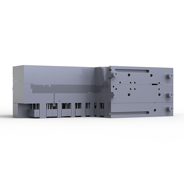
Gating and venting strategies control the entire molten metal fill process. You must position gates to ensure uniform, unidirectional metal flow. Elongated pedal arms require smooth, uninterrupted filling to prevent turbulence. High gate velocities cause air entrapment and degrade the final mechanical properties. We strongly recommend utilizing high-vacuum die casting configurations for these projects. Vacuum systems effectively eliminate trapped gas inside bulky mounting nodes. This significantly reduces dangerous gas porosity in critical load-bearing joint areas. A well-designed vacuum block ensures the cavity evacuates milliseconds before injection.
A reliable custom automotive pedal die casting mold relies heavily on advanced thermal management. You must map cooling channels strategically to address all localized thick sections. Heavy bosses and pivot points hold excessive heat for extended periods. Dedicated cooling lines positioned near these features prevent localized shrink porosity. Conformal cooling plays a massive role in reducing overall cycle times dramatically. Standard straight-line drilling simply cannot reach complex geometric curves effectively.
Here are the essential steps for successful conformal cooling integration:
Finally, you must specify adequate draft angles for reliable part ejection. Long structural ribs and deep pockets require at least a 1° to 2° minimum draft. This prevents severe ejection galling and extends your overall mold wear life. Insufficient draft causes the aluminum to drag against the tool steel surface. This dragging creates deep scratches and requires immediate, costly polishing downtime.
Choosing the right tool steel completely determines your long-term production success. Standard commercial steel grades fall incredibly short for large automotive components. They simply cannot withstand the severe thermal shock of continuous aluminum injection. Molten aluminum enters the die at approximately 670°C under immense pressure. You must require NADCA-compliant premium H13 or SKD61 tool steels always. Proprietary high-impact steels like Dievar offer even greater resilience against microscopic heat checking. Heat checking creates tiny surface cracks that eventually propagate into massive tool failures.
Heat treatment and surface engineering require uncompromising, documented quality control. Hardness requirements for the core blocks typically fall between 46 and 50 HRC. This specific hardness range perfectly balances core toughness against vital surface wear resistance. We also highly recommend exploring advanced PVD (Physical Vapor Deposition) coating options. These specialized ultra-hard coatings prevent molten aluminum from soldering to the die surface. Soldering causes severe cosmetic defects and forces operators to halt production frequently.
You must establish realistic predictive maintenance assumptions very early on. Large pedal molds face immense mechanical stress during every single clamp and inject cycle. You can expect a typical safe shot life ranging from 80,000 to 100,000 shots. After reaching this threshold, the tooling requires major inspection and refurbishment. Planning for this mandatory downtime prevents unexpected production halts. Best practices include scheduling stress-relieving tempering cycles every 10,000 to 15,000 shots. This routine maintenance drastically extends the ultimate lifespan of your automotive pedal die casting mold.
Tool Steel Grade Comparison for High-Volume Casting
| Steel Grade | Thermal Fatigue Resistance | Machinability | Ideal Application Area | Relative Cost |
|---|---|---|---|---|
| Standard H13 | Moderate | Excellent | Non-critical mold bases | Base Level |
| Premium H13 (NADCA) | High | Good | Main cavity and core inserts | Moderate |
| Dievar / High-Impact | Very High | Fair | Complex gates and thin ribs | Premium |
Partnering with a highly reliable automotive pedal die casting mold supplier mitigates immense financial risk. Technical vetting criteria during the sourcing phase must remain incredibly strict. You should rigorously verify if they perform mandatory MagmaSoft or Flow-3D mold flow simulations. They must complete these advanced digital analyses before finalizing any sizing dimensions. These simulations reveal hidden air entrapment pockets and unfavorable flow vectors instantly. Furthermore, verify their in-house heavy machining capabilities firsthand. They need large-scale CNC and EDM equipment specifically sized for heavy-tonnage mold bases. Subcontracting these crucial machining steps introduces unacceptable quality control vulnerabilities.
Quality and compliance frameworks are entirely non-negotiable in the global automotive sector. Ensure the supplier actively holds mandatory IATF 16949 and ISO 9001 certifications. Traceability across the entire manufacturing process ensures consistent, repeatable tooling quality. Demand complete, unedited documentation for all raw steel origins and material certificates. You should also deeply review past heat treatment charts and detailed CMM inspection reports. A trustworthy supplier readily provides this data without any hesitation.
When moving to the final shortlisting phase, apply a structured logical sequence. Request a comprehensive Design for Manufacturability (DFM) report based on your initial CAD data. Evaluate their specific engineering feedback on wall thickness transitions and gating locations. Do they simply accept your design, or do they propose structural improvements? Finally, compare their rapid prototype tooling capabilities against hard production tooling timelines. A top-tier supplier can deliver rapid prototypes while simultaneously cutting production steel. Every vetted step mathematically secures your final capital tooling investment.
To guarantee high-yield pedal casting production, keep these critical next steps in mind:
A: The ideal machine tonnage typically ranges from 600T to 1200T for large, integrated automotive pedal castings. This heavily depends on the overall projected area and whether you utilize a single or dual-cavity layout. Complex brackets combined with accelerator modules require higher clamping forces. This added tonnage effectively prevents die flashing and ensures dimensional stability under peak cavity pressures.
A: Manufacturing typically requires 6 to 10 weeks from initial order to the first article testing (T1). This timeline includes comprehensive Design for Manufacturability (DFM) reviews and intensive mold flow analysis. Subsequent steps involve rough machining, specialized heat treatments, and precision CNC finishing. Requesting highly complex conformal cooling channels or intricate vacuum venting systems may extend this timeline slightly.
A: An undersized mold leads to severe manufacturing defects. Inadequate clamping force causes the die halves to separate slightly during injection, resulting in excessive metal flashing. This instability also triggers severe dimensional warping across the pedal structure. Furthermore, poor pressure retention within the cavity creates severe porosity, completely compromising the mechanical strength of the final automotive component.
A: Yes, the specific aluminum alloy drastically affects mold sizing requirements. Different alloys, such as A380 versus AlMg5Si2, possess varying natural shrinkage rates and unique flow characteristics. Engineers must scale the die cavity precisely to match the chosen alloy's shrinkage behavior. Failing to accommodate these specific metallurgical properties guarantees out-of-tolerance dimensions and high scrap rates during final assembly.


