

Views: 0 Author: Site Editor Publish Time: 2026-09-03 Origin: Site


Choosing the wrong tooling capacity derails production timelines and inflates upfront capital expenses. Under-specifying mold capacity leads to premature tool failure and severe production bottlenecks. Over-specifying ties up your budget in unnecessary tooling longevity. You cannot afford these miscalculations in today's competitive landscape.
The shift toward EV powertrains changes everything. You now face highly complex, tight-tolerance die-casting challenges. This reality raises the stakes for accurate capacity planning. You must choose your manufacturing partner carefully to navigate these shifting demands.
This guide provides a clear framework for alignment. We will align your project’s volume, technical requirements, and lifecycle goals. You will learn how to choose the exact tooling specifications and partner you need to succeed.
Mold capacity is a function of expected production volume (tooling life/shots) and required clamping force (machine tonnage).
High-pressure die casting for EV motor housings requires specific thermal management and structural integrity to prevent porosity.
Evaluating a supplier requires looking past unit price to assess IATF 16949 compliance, PPAP maturity, and in-house tooling maintenance capabilities.
Clearly defined tolerance specs and trial phase (T0/T1) criteria are critical to mitigating launch risks.
You must correctly forecast your production lifecycle. We separate tooling into distinct industry classifications based on projected shot life. Class 101 molds handle high-volume demands effortlessly. They endure over one million cycles. They suit long-term, mainstream EV platforms perfectly. Class 103 molds accommodate medium volumes. You can expect up to 500,000 cycles here. They save substantial upfront capital. We strongly recommend Class 103 configurations for niche vehicle models or localized production runs.
Calculating the required clamping force requires precision. You must analyze the part size thoroughly. Projected surface area dictates the baseline pressure needed. Material flow dynamics also play a critical role here. Viscous aluminum alloys require immense injection pressure. Underestimating machine tonnage causes severe flash defects along parting lines. Overestimating tonnage forces you into unnecessarily large machines. This mistake artificially inflates your hourly production rates.
Prototyping demands extreme agility. Single-cavity configurations serve low-volume EV needs exceptionally well. They validate complex designs quickly. They also allow engineers to tweak wall thicknesses easily. Legacy platforms demand rigorous scale. Multi-cavity setups handle high-volume demands efficiently. They reduce piece prices significantly over the vehicle lifecycle. You must decide your scaling trajectory before cutting any steel.
Balance initial capital expenditures wisely against long-term piece-price amortization. High upfront costs often lower per-part expenses over five years. Cheap tooling risks frequent breakdowns and expensive line stoppages. Evaluate your lifecycle volume realistically. Spending more on premium steel today often prevents catastrophic launch delays tomorrow.
Mold Class (SPI Standard) | Expected Shot Life | Primary Application | Cost Profile |
|---|---|---|---|
Class 101 | 1,000,000+ | Mainstream High-Volume EV Platforms | High CapEx, Lowest Piece Price |
Class 102 | Up to 1,000,000 | Standard Mid-Volume Production | Medium-High CapEx |
Class 103 | Up to 500,000 | Niche Models / Regional Launches | Medium CapEx, Balanced Piece Price |
Class 104 | Up to 100,000 | Prototypes / Bridge Tooling | Low CapEx, Higher Piece Price |
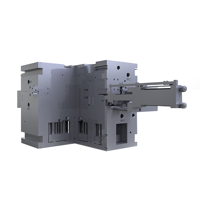
Tool steel takes massive abuse during casting cycles. You must choose premium H13 or highly customized die steel grades. These robust materials resist immense thermal shock consistently. Casting a high pressure aluminum automotive electric motor housing introduces wild temperature fluctuations. The molten aluminum hits the steel violently. Weak steel develops spiderweb cracks quickly. These cracks ruin the cosmetic finish and compromise dimensional accuracy.
Cycle times dictate profitability entirely. We rank thermal management as the highest design priority. Standard straight-line cooling channels often fail here. They leave dangerous hot spots behind.
Analyze thick-walled sections: Motor housings contain varied wall thicknesses. Identify the thickest regions first.
Implement conformal cooling: These curved channels hug the part geometry closely. They extract heat uniformly.
Balance flow rates: Ensure water pressure remains consistent across all circuits.
Monitor thermal fatigue: Uniform cooling prevents steel degradation over thousands of cycles.
Electric motors require integrated liquid cooling to function. Creating these internal water jackets challenges toolmakers severely. Tooling requires precise internal geometry to form these pathways.
Sand Cores: Some designs utilize expendable sand cores to form intricate internal channels.
Specialized Sliders: Mechanical sliders manage complex undercuts successfully.
Core Pulling Sequences: You must sequence core movements flawlessly to avoid tearing the cooling jacket walls during ejection.
We see similar metallurgical demands in heavy-duty automotive applications. The durability required for an alloy wheel mold mirrors these extreme thermal challenges. However, electric motor housings diverge sharply regarding precision. Wheel molds allow broader tolerances. Motor housings demand vastly tighter geometric precision. Bearing bores allow zero room for error. You must establish stringent automotive motor housing mold specifications to achieve this concentricity.
Active IATF 16949 certification remains non-negotiable. It separates capable partners from dangerous liabilities. You must verify strict adherence to AIAG core tools. APQP guides the entire development phase safely. FMEA identifies potential failure modes early. MSA ensures their measuring equipment reads accurately. SPC monitors their production stability consistently. PPAP guarantees they can mass-produce the automotive motor housing mold parts repeatedly.
Brokers add unnecessary layers of risk. You lose direct control over project timelines. We advise choosing a direct automotive motor housing mold supplier instead. Look deeply into their facility structure.
Do they operate on-site CNC machining centers?
Can they repair tools in-house rapidly?
Do they outsource core slider mechanisms to third parties?
On-site tool-repair facilities ensure rapid maintenance turnarounds. Outsourced repairs cause devastating production line stoppages.
Design for Manufacturing (DFM) prevents costly disasters later. Capable suppliers perform extensive mold flow analysis proactively. This simulation predicts defects accurately before steel cutting begins. It highlights porosity risks clearly. It maps potential shrinkage zones. Warpage issues become visible early. We value suppliers who challenge poor design assumptions. They save you from unmanufacturable geometries.
Demand total transparency during the quoting phase. Hidden costs destroy program budgets quickly. Request clear maintenance schedule breakdowns upfront. Spare parts inclusion should be obvious and itemized. Engineering change request (ECR) pricing needs strict boundaries. Ambiguity here allows suppliers to price-gouge you during minor design tweaks.
Gas entrapment plagues high-pressure die casting inherently. It compromises structural integrity severely. Motor housings must remain leak-proof to protect internal electronics. Vacuum-assisted die casting mitigates this risk effectively. It extracts air from the cavity just before injection. Precise gating design also solves flow-related porosity. Strategic venting allows trapped gases to escape quickly. You must demand flow simulation proof from your partner.
Thermal expansion alters tooling dimensions during long runs. Tool wear impacts concentricity directly over thousands of cycles. Bearing bore alignment shifts gradually. You must monitor these changes constantly. Implementing strict CMM checks catches drift early. Regular preventative maintenance restores dimensional integrity.
Establish a rigid metrology schedule. Measure critical bearing seats every 1,000 shots. Keep extra slider inserts in stock. Replace worn components before they exceed the upper control limit.
T0 and T1 phases serve completely different purposes. Misunderstanding them causes massive friction between buyers and suppliers.
Trial Phase | Primary Focus | Success Criteria |
|---|---|---|
T0 (First-Off-Tool) | Mold Functionality | Tool opens/closes smoothly; parts eject without sticking; no flash on parting lines. |
T1 (Dimensional Trial) | Dimensional Compliance | CMM data matches print; bearing bores within ±0.02mm; surface finish acceptable. |
T2+ (Optimization) | Process Stability | Cycle time targets met; scrap rate stabilized; PPAP documentation finalized. |
T0 focuses entirely on mechanical mold functionality. Does it open smoothly? Does it eject parts cleanly? T1 shifts focus toward dimensional compliance. You verify exact measurements here. Set realistic success criteria for both stages to avoid launch panic.
Suppliers often quote highly optimistic cycle times to win bids. You must verify these assumptions vigorously. Real-world thermodynamic limits dictate true cooling speeds. Rushing cooling cycles causes severe part warpage post-ejection. Delayed production schedules often stem directly from unrealistic timing estimates. Challenge their cooling channel flow rates during the design review.
Build a highly comprehensive Request for Quote. Ambiguous RFQs yield wildly varying bids. This makes apple-to-apple comparisons impossible. Include annual usage projections clearly. Define exact material specifications. Detail surface finish requirements upfront. Specify the exact shot guarantee you expect. Outline who pays for expedited shipping if trial phases fail.
Facility walk-throughs reveal critical truths. You cannot judge capability purely through PowerPoint presentations. Inspect toolroom cleanliness first. Disorganization signals deeper quality control issues. Evaluate their CMM inspection capabilities thoroughly. Do they have climate-controlled metrology labs? Review actual die maintenance logs on the shop floor. Past behavior predicts future performance reliably.
Do not spend all your time in the conference room. Do not ignore the tool maintenance storage area. Rust on spare inserts indicates poor preservation standards. Always speak directly to the CNC operators.
Weigh multiple factors objectively when finalizing your choice. Tooling cost matters significantly, but it rarely dictates ultimate success alone. Lead time impacts your vehicle launch date directly. Technical DFM feedback demonstrates actual engineering expertise. Geographical supply chain risks demand careful evaluation. Choose structural stability over minor initial savings.
Selecting the right mold capacity requires aligning your program's lifecycle volume with hard engineering realities. You cannot guess machine tonnage or thermal dynamics. You must calculate them rigorously. Treat tooling classification as a strategic business decision, not just a procurement checkbox.
Prioritize suppliers who challenge your DFM assumptions aggressively. They protect you from poor designs. Demand transparent tooling maintenance plans over those who simply provide the lowest initial tooling bid. Establish clear success criteria for T0 and T1 trials immediately. Follow this framework to launch your motor housing project smoothly, predictably, and profitably.
A: Standard requirements include premium H13 steel and 80,000–100,000 shot minimum guarantees. Critical areas, especially bearing seating surfaces, demand tight geometric tolerances down to ±0.02mm. They also require conformal cooling systems to handle rapid thermal cycling effectively.
A: Realistic lead times generally range from 8 to 12 weeks. This covers design, CNC machining, and T0 sampling. Highly complex designs utilizing multiple sliders or intricate sand core requirements often push this timeline closer to 14 weeks.
A: Mold flow simulation prevents costly physical rework. It identifies air traps, cold shuts, and suboptimal gate placements digitally. By fixing these flow dynamics on a screen, you avoid creating thousands of porous, defective aluminum castings during physical manufacturing.


